In current-carrying veins of wires and cables, current flows in the right direction. And the insulating coating of these cores prevents the passage of current to places where it can not appear. This eliminates the accidental contact of people with live parts, prevents short circuits in distribution networks.
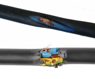
But sheaths of conductors are fragile. Already in the process of laying the cable, they can be transferred or torn off on the sharp edges of objects falling on the track. When cutting cable ends, you can accidentally cut the insulation of live conductors with a knife. When soldering, polyvinyl chloride melts and loses its insulating properties, and the rubber dries and cracks over time, exposing the conductors covered by it.
After the correct equipment is designed for the required application, the engine work plan should provide for preventive maintenance in accordance with its classification in the equipment park and even with the established operating mode. Another parameter that should be taken into account in this case in already completed operations is the number of failures in one equipment or area. That is, even if the engine does not have a large impact on production, the high frequency of failures in this area indicates what preventive actions should be taken to identify the cause and find a final solution to the problem.
Reasons for insulation degradation
Contributes to the deterioration of the insulation properties of cables and local heating of contact joints. Heat, spreading through a metal core, heats the coating material, reducing its insulating properties. This applies to junction boxes, and to the places where the conductors are connected to circuit breakers, zero buses, sockets.
In some cases, failure may be caused by exposure to elevated temperatures. The Brazilian standard sets the temperature limits for motor winding, depending on the thermal class of insulation materials that were used in its manufacture.
Thus, in order to correctly measure the temperature of the field in the field, it is necessary that the equipment has temperature sensors on the winding, which is not a reality for many models in operation. However, for the external measurement there are no restrictions established by standardization, and, therefore, engine manufacturers indicate some methods for carrying out this activity. Firstly, it should be borne in mind that the temperature outside the motor is much lower than the winding. In addition, its value varies depending on the point on the surface at which it is measured.

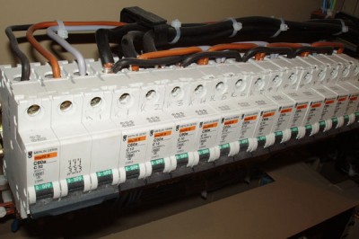
Cases of switching devices: switches, circuit breakers, circuit breakers - are made of insulating materials. Decrease in isolation occurs if dust, dirt, metal filings settle on them. Reducing the insulation properties contributes to overheating of the cases, carbonization of them after short circuits.
Insulation Resistance Test Frequency
Therefore, it is ideal that the ambient temperature is measured at a maximum distance of 1 meter from the engine. On the other hand, the housing temperature should be based on the upper lateral center of the motor, while it is recommended that the temperature of the bearing connected to the side be measured as shown in the illustration on page
Unlike temperature, vibration can be measured based on generally accepted standards. They determine the points where measurements must be taken, as well as the limit values \u200b\u200bthat must be taken into account. They show six measurement points, as shown in the table above. It is important to note that the measuring points should be as close as possible to bearings that are always in hard parts. Vibration should not be measured in areas of the housing that are not too close to the covers.
Electrical switchboard scourge - humidity. Damage to pipelines, condensation, flooding of basements with distribution devices - all this leads to the appearance of water droplets between the terminals of electrical equipment under different electrical potentials. Water in its pure form does not conduct electric current. But, getting on the dirt and dust covering the body of electrical appliances, it dissolves the substances in it, becoming a conductor of electric current. A short circuit occurs.
Given priority preventive maintenance, that is, in accordance with the importance of the engine for the operation, level A equipment can undergo vibration analysis every 30 days, while level B every 60 days. Such methods can help identify bearing problems and, in more specific cases, detect electrical failures, such as interruption of rotor rods. In addition, vibration analysis helps identify problems associated with imbalance and misalignment of kits.
Measurement of insulation resistance is part of the periodic tests and can only be performed when the electrical installation is turned off. However, power outages are often associated with high costs of interrupting the process and time-consuming recovery processes, and in some applications is not practical. Technical standards offer alternatives, as this article demonstrates.
The greatest risk to meet damaged insulation occurs after installation work. The second peak of problems is already encountered in operation, some years after installation. A separate view is the damage associated with improper operation electrical appliances and wiring, flooding the apartment with neighbors and nails driven into the highway when trying to hang a picture on the wall.
Michael Faust and Jörg Irzinger from Bender. To ensure the safe operation of installations requiring high availability, the standards allow two possible measurement methods without disconnecting the voltage. Differential current measurement for grounded power supplies; and continuous measurement of insulation resistance, for isolated neutral sources. In grounded networks, the total differential currents of the installation can be measured and continuously evaluated using residual current monitoring devices. This procedure recognizes and emits an alarm when insulation is degraded.
The difference between a megohmmeter and a multimeter
The machine turned off, the apartment plunged into darkness. The reason is a short circuit. It is necessary to find the place of damage, otherwise there will be no light. If, as a result of overheating, two cores are closed between themselves in a junction box or in a cable, you can find it and multimeter in resistance measurement mode. On a faulty pair, he will show zero. But this is a simple case.
Another possibility for isolated systems is the use of insulation monitoring devices that constantly measure insulation resistance. Both alternatives do not require power off during periodic testing. Safe operation of the facility is subject to numerous laws, rules and standards that define safety limits. In this context, periodic tests are important, which can be carried out to a large extent with commissioning, with the exception of the measurement of insulation resistance specified in the standards.
The carbonized insulation section has a resistance far from zero. A small current flows through it, heating the shell, gradually worsening the insulation. At some point, a breakdown occurs, the current increases sharply, the protection is triggered. The damaged area cools instantly, its resistance increases. The multimeter will show that it is equal to an infinitely large value. In order to avoid such damage, you need a device that, when measured in the circuit under test, produces a voltage comparable to or greater than the voltage in the network. Such a device is a megaohmmeter.
To measure the insulation resistance between live parts and a grounded protective conductor, the installation must be turned off. In fact, standards regarding plant operation, as well as other rules, offer alternatives in accordance with the appropriate network grounding scheme, as shown below.
Grounded power supply
According to the mentioned documents, grounded systems can be equipped with differential current monitoring devices, as already mentioned. The operator is automatically notified by e-mail of deterioration of insulation, which leads to measurable changes in leakage current. The availability of the installation increases, at the initial phase side currents are detected, and the cost of measuring the insulation of the installation and components during periodic testing is also reduced.
Megaohmmeter device
For measurements this device gives direct current to the circuit under test. A variable is not suitable for this purpose, since all cable lines have capacitive resistance. And capacitors conduct alternating current. This will lead to a distortion of the measurement results.
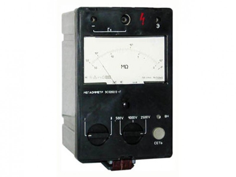
Depending on the operating voltage of the network and the equipment under test, megaohmmeters with voltages of 100, 500, 1000 and 2500 V are produced. Stovolt meters are used to test the insulation of low-voltage cables and semiconductor equipment, and for 500 V - windings of electric machines of small power. Instruments with a voltage of 2500 V are designed for measurements on high-voltage devices, cable and overhead lines. Which device to choose for measurements - is indicated in the normative and technical documentation for commissioning or operation, PUE, passports for electrical equipment.
Isolated power supply
For installations whose closure or unplanned closure is costly, isolated neutral systems are an alternative with several advantages. If there is a deliberate lack of a connection with a low impedance between the star point of the transformer and the ground, the occurrence of the first insulation failure does not lead to high fault currents. This leads to very good EMC characteristics, power outages and safety on the first error.
To measure insulation resistance in household lighting and outlet networks, megaohmmeters with a voltage of 1000 V are used.
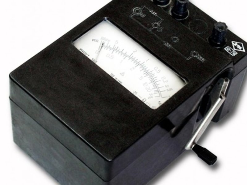
In obsolete designs of megaohmmeters, a generator was used to generate the measuring voltage, the rotor of which was rotated by the handle. It was untwisted to a speed of 120 revolutions per minute, otherwise the output voltage turned out to be lower than the nominal. The measuring mechanism of such devices is analog, with a scale and an arrow. The scale was divided into two parts - upper and lower, corresponding to two ranges of resistance measurements. The marks on the scale were uneven, which complicated the reading. It wasn’t very convenient to take these readings while rotating the megohmmeter knob - the instrument body twitched, the arrow jumped. In addition, both hands were occupied by the user: one, he held the device in place, the other - twisted the handle. The measuring probes on the contacts were held by his assistant, or they were soldered to them with crocodile clamps.
All other standardized tests and checks, such as measuring the impedance of the terminal loop, are usually performed, but do not require interruption of the installation. Impregnated cables at the end of their service life, defective synthetic insulation cables after a limited number of years of service: the risk of failure is real and the financial consequences can be significant.
Cable diagnostics go beyond simply stating the current operational reliability of a cable. Diagnostics refers to the analysis of the current state, as well as to trends in the state of cable insulation. Insulation aging causes cable loss. Thermal overload, moisture penetration or junction boxes and improperly machined ends also contribute to these losses. These processes occur over a long period.
For each measuring voltage its own megaohmmeter was produced. Only a model of the ESO 202 type contained a switch for 500, 1000 or 2500 V. To carry out measurements, a whole fleet of megohmmeters was contained in the electric laboratories.
Cost of measuring insulation resistance
Diagnostic methods used: Delta-tangent measurement, also known as loss angle measurement or dispersion coefficient. Partial Discharge Measurement The equipment used is very low voltage generators. This measure classifies cables according to 3 categories: Healthy cable \u003d monitoring every 5 years. Cable represents low risk \u003d biennial or even annual monitoring. Cable with significant risk \u003d corrective actions that are planned.
Modern devices have become semiconductor. The choice of measurement limits for them is automatic, and the test voltage is selected before measurement in the menu or using the switch. The dimensions of the device allow it to be held in the hand together with one of the probes, which allows measurements to be made individually. Some models are equipped with a start button on one of the probes.
Additional diagnostics by measuring partial discharges
The origin of partial discharges in the cable is due to vacuoles present in the dielectric. These vacuoles are potential points of weakness. Indeed, under the influence of alternating voltage, the insulation is exposed to an electric field, the distribution of which may be inhomogeneous due to the heterogeneity of the insulation. In the vicinity of vacuoles, the electric field gradient can then reach a destructive value and cause an arc of destruction that neutralizes the gradient. Similarly, the presence of a conductive particle in the insulator can also cause a discharge.

But many modern megaohmmeters have one significant drawback, which translates them into the usual probe mode. According to the rules, the measured insulation resistance is the value shown by the device 60 seconds after the start of the test. Most models issue a test voltage for a few seconds and do not have a continuous voltage generation mode. Not all defects can be detected in such a short time.
Depending on the state of degradation at the same point, it is possible to have several tens of localized discharges. Solid insulators usually do not regenerate after discharge. Thus, discharges gradually degrade insulation by erosion, first on the surface of the cavity, and then deeper, which ultimately leads to destruction of the dielectric and destruction of the cable.
A partial discharge measurement can find these weak points in the cable. Note. Measurement of insulation or testing of dielectric cables does not allow to evaluate the quality of insulation. In fact, the measurement of insulation may vary depending on the length of the network, the method of injection or the capacity of the cables. In addition, insulation measurements do not detect cables with potential faults such as a spark gap, while dielectric testing should be avoided during preventative maintenance. This test, potentially damaging, causes unnecessary stress to the cable.
Rules for conducting megaohmmeter measurements
Megaohmmeter refers to devices that measure the characteristics of electrical equipment associated with determining its feasibility safe operation. And on its conclusions during measurements is present life-threatening stress. Therefore, its use is possible in cases:
- The device must undergo metrological verification once a year.
- Using a megaohmmeter is allowed for trained personnel.
- Only a licensed electrical laboratory has the right to issue a protocol with a conclusion on the suitability of electrical wiring for further operation. Measurements taken by other persons do not have legal force.
If you have a megohmmeter at your disposal, then you can measure the insulation resistance only on personal initiative. We completed the installation of electrical wiring to a neighbor, measured - we were convinced of the absence of defects. But if when connecting a neighboring house to the network, the power supply organization will require a measurement protocol - your work will not be counted. A neighbor will have to call specialists and pay them money for the same work.
Why is this necessary?
The dielectric test allows you to: qualify the implementation of the cable and its accessories. This must be done before commissioning the cable for the first time. To check, after repair, the quality of work performed on the cable. For more information, contact an apav specialist.
Contact our agents. A thorough knowledge of the physical characteristics of insulating materials contributes to the development of energy-efficient buildings. The laboratory has the great ability to pack products with precise and varied temperatures and humidity.
In kindergartens, schools, institutions and enterprises insulation resistance of electrical wiring is measured regularly. The results are recorded in protocols that are required by representatives of the fire department and energy supervision. The registration documents of the laboratory that performed the measurements are attached to the protocols. Without them, they are a useless piece of paper.
Indices of insulation resistance of electrical wires
In particular, for bulk insulating products, the laboratory is equipped with a device for purging and insufflation. It simulates the implementation of a product and measures the density of the product used. This laboratory can also characterize the mechanical strength, compaction, heat resistance and humidity of an insulating product or process.
The laboratory has specialized equipment for measuring the mechanical characteristics of products. Resistances measured in tensile, shear and compressive forces allow us to characterize the use for which the products are intended in the building, in accordance with the limitations that they will suffer afterwards. And this, in accordance with the texts of the link.

If a fire occurs in the organization’s premises, the first thing they need from its leaders is insulation measurement protocols. If there are none, the perpetrators are automatically determined. The same thing happens when an employee is shocked by electric current. Even if he himself put a screwdriver into the socket, holding on to its rod. If during the investigation of the accident the isolation measurement protocol is not found, the management is provided with problems.
Nevertheless, a megohmmeter is a device useful for people involved in the installation of electrical wiring. Better to find a defect right awaybefore the arrival of specially trained persons. Otherwise, they will come again, after fixing the defect. Laboratory staff is not required to look for it on their own. Upon returning, they will force the owner to pay an additional amount for the work. Most likely, he will deduct it from your fee.
After replacing the wiring in the apartment, insulation measurements are not officially required. Therefore, it will not hurt to fulfill them for complacency, and in the eyes of the client your rating will only increase in the end.
Rules for measuring insulation with a megohmmeter
Before each use, any megaohmmeter is checked test lead insulation integrity. This is important, as damage leads to electrical injuries.
On a megohmmeter, the necessary test voltage then check serviceability of the measuring circuit and instrument. For this, the probes are short-circuited and measured. The device will show zero. The probes disconnect and measure again. The device will show infinity. These manipulations are carried out regularly in order to timely detect lost settings, a broken wire, weakened contact or a malfunction of the megohmmeter.
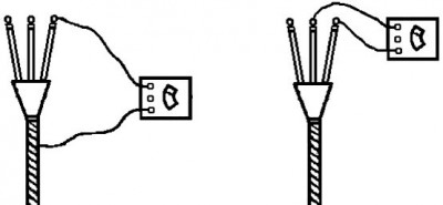
Rules for measuring insulation resistance require that for the cable line, the insulation between the cores was measured in all possible combinations. For a three-core cable - three dimensions, for a four-core cable - six, five-core cable - ten. In reality, this test can be implemented by having a cable with disconnected cores. Disabling them for verification after installation is a complicated operation.
Since in systems with a grounded neutral zero working and protective conductors are interconnected, then the device between them will show zero. But, even if you disconnect the power cable from the object, all the zero working and protective conductors combined on the buses will show the same resistance to each other. If it fits into the norm, then everything is fine. And if not, you will have to disconnect them from the tires in turn, watching for changes in insulation.
A simplified measurement method for outlet groups is to measure the resistance of the phase conductor from the power supply circuit breaker with respect to the zero and PE bus.
For the lighting network, everything is more complicated. Under the phase potential during the operation of the luminaires, there is a section from the power supply unit to the lighting device passing through the switch. If you do not turn the lamp out of the lamp, the device will show its resistance. Therefore, when measuring the insulation resistance of lighting networks, the lamps are turned out, and the switches are turned on. This tests the area that is actually under voltage in operation.
And do not forget about semiconductor ballasts. They have a rectifier at the input. In order not to damage it, disconnect the wires from the lamp. Although modern megaohmmeters, sensing something was amiss, sharply reduce the test voltage to a minimum value. Semiconductor elements rarely fail, but you should not try your luck once again.
Measurement results for household wiring should keep within 0.5 megohms. Anything below this bar must be eliminated. In fact, new cable lines have insulation resistance of hundreds and thousands of megaohms. Values \u200b\u200bbelow hundreds are typical of old wiring, and even worn out.
An electric cable and wire are an integral component of absolutely any power supply system and, like any electrical equipment, they require constant attention. Electrical wiring and cable lines immediately after and during operation must be measured with insulation resistance. During manufacture, during transportation to warehouses and facilities, the cable is constantly subjected to mechanical stress.
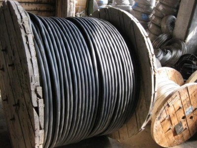
Drums and bays with cable and wire are rolled, dragged along the ground, thrown from place to place. In addition, they lie in the open air and scorch under the sultry sun or freeze in 40 degree frosts. Naturally, under the influence of precipitation, high and low temperatures, the insulation begins to age prematurely. Unfortunately, most electricians ignore these facts and perform cable wiring without first checking. In addition, installers very often violate the installation technology and lay the cable with gross violations. Therefore, to guarantee the quality of insulation of conductors walled in walls, floors and ceilings, can only measure the insulation resistance.
During operation, cable lines and wiring also have a hard time. Very often, when installing powerful modern equipment and equipment that consumes a large amount of electricity, I do not take into account the fact that this electrical installation is simply not designed for such power. As a result, the conductors overheat during operation, their insulation wears out and quickly ages, and the circuit breakers constantly disconnect the load. Some enterprising people solve the last problem by installing an over-rated protection device, thereby rendering the insulation of the conductors unusable.
Since wires with worn insulation that are unprotected from overload can one day cause a fire. Periodic measurement of insulation resistance allows you to identify all these problems and timely eliminate them. Otherwise, they will, at a minimum, lead to leakage of electricity, and, as a maximum, to or fire.
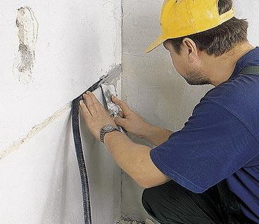
Measurement of insulation resistance begins from a visual inspection. When inspecting cable lines and electrical wiring, the specialists of the electric laboratory first of all check their external insulation for visible damage and defects. Please note that in places of cable bends, passages through walls, entry points into switchboards, it must be protected from mechanical damage. During visual inspection, special attention is paid to the fused ends of the insulation, since this indicates that the cable (wire) was very hot during operation. The reason for this may be a poor connection of the conductors to the terminals, a malfunction or an overvaluation of the circuit breakers.
After a visual inspection, they begin to measure the insulation resistance. Tests should be performed on a disconnected electrical installation, that is, all conductors to be checked must be de-energized without fail, and electrical equipment disconnected from the network. When measuring the insulation resistance of lighting circuits, all lamps must be unscrewed from the lighting fixtures, and the switches are on. Measurement of insulation resistance is carried out, specially created for these purposes, by a device - a megger.

At the same time, it is impossible to use instruments for measuring insulation resistance that have not passed annual verification. As a rule, insulation resistance is measured between phase conductors, phase and neutral working conductors, phase and zero protective conductors, as well as between zero working and protective conductors. That is, the number of measurements depends on the number of wires in the line. In this case, the smallest permissible value of the insulation resistance must be at least 0.5 MΩ.
If the measured reading is less than this value, then the cable line can be divided into sections, starting from the switchboard, and measure the insulation resistance of each received section. A cable (wire) with defective insulation is subject to immediate repair or dismantling and replacement.
Read also:
Vitaliy Hello. And who can measure the insulation resistance already in the existing wiring? Does the repair and maintenance personnel (electrician on duty) have the right to do this with a simple megger meter and will such measurements be valid? Resistance Measurements ...
Stanislav We built a lighting line of 23 poles. The cable between the supports is laid in the ground. Each support has a cable cut. To put the line into operation, we are forced to take measurements of insulation resistance ...
Elena We have a medical center in Moscow, we need a measurement of insulation resistance. There are electrical appliances that can not be turned off from the outlet, but I want to have a complete picture. How to be Thanks. To perform a complex of electrical measurements, ...
Vladimir An energy surveillance officer ordered us to call an electrical laboratory and measure the insulation resistance of the input (supply) cable. An input cable is laid from the VL support to our store. In order to measure the insulation resistance, we ...