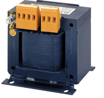
The household electrical network has a voltage of 220 volts, which is designed for most electrical appliances. In this case, often there is a need to lower the voltage to 12 V to power individual consumers - low-voltage heaters, halogen lamps and power to other devices (LED strips, etc.) designed for alternating current. This is provided by a transformer, which has a small size and a one-piece housing.
The device can be picked up and purchased in retail chains, and, if necessary, made with your own hands.
Design, principle of operation
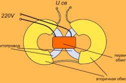
 A standard transformer for undervoltage consists of 2 windings (primary and secondary), wound on a ferrimagnetic core with a copper wire. The primary is connected to the network, and the secondary to the load. Principle of operation such a device is as follows:
- The voltage applied to the primary winding generates an alternating field around the core.
- When connected to a load, magnetic induction generates voltage in the turns of the secondary winding, and the energy supplied to the secondary circuit will come from the primary winding.
The magnitude of the output voltage is influenced by the ratio and number of turns of each winding. By adjusting this indicator, you can achieve any value of the current on the secondary winding, and get both lowering and. It should be borne in mind that a device connected to a 220 V household network will produce an alternating voltage, which, if necessary, can be converted by a rectifier.
At present, electronic type reduction devices made by semiconductor basedwhose work is complemented by an integrated circuit. They have certain advantages in the form of small size, high efficiency, low weight, lack of heating and noise, the possibility of adjusting the current, protection against short circuit. But the traditional transformer continues to be actively used because of the reliability and simplicity of the design.
The choice of a ready-made solution, criteria
Electrical and electronics stores offer ready-made household transformers for various needs. Choosing the right device, you need to be guided by the following criteria:
- Input voltage parameters. The device case must be marked with 220 or 380 V. In this case, a household option is needed for a 220 volt network.
- Input voltage parameters that must correspond to 12 V.
- By power. To do this, preliminarily calculate the total load, which will be powered through a transformer. This indicator of the device must exceed the calculated value by at least 20%.
Using a transformer that converts 220 to 12 V, you can save a lot on protective materials and cable by implementing a domestic lighting system on its basis, using halogen lamps and LED strips. This is a safe circuit in terms of electric shock, moreover, protected from power surges and short circuits. Such systems exclude the possibility of fires.
On the video, a story about buying a turnkey solution
Varieties
Step-down transformers are classified based on the type of execution (open or having a housing) and by application (industrial, domestic). Also devices are shared by way of fastening:
- A rod, in which the windings are collected around the rod, and it is installed only in an upright position.
- Armored, in which the armored winding is used, allowing you to install the device in any position.
Review of ready-made models
Among ready-made device modelspresented in electrical stores for converting the current of a household network 220 to 12 volts, the following can be noted:

Average prices by region
Depending on the location of the region, the price of the same transformer may vary. For example, the transformer CCA 0.25 220/12 in different cities will have different cost:
Do it yourself
If it is necessary to manufacture a step-down transformer from 220 to 12 V, after calculating the power of the product, they begin to acquire the necessary materials. To do this, you will need:
- Core. You can use this part of a suitable size from a failed television transformer.
- Enameled copper wire of the required cross section.
- Tape insulation (varnish), paraffin paper and cardboard.
The windings of coils can be done manually or made for this with your own hands a simple winding machine, the circuit of which is freely available on the network. Product size will depend on the size of the core. If it has the shape of a ring, then the winding of the turns will have to be done manually.
The self-manufacturing process of the transformer consists of the following steps:
Calculation of characteristics and number of turns of the future device. The calculation is based on the voltage of the primary network (220V), as well as its parameters at the output and core section. For example, if its area is 6 cm 2, then the constant for the average transformer metal, equal to 60, is divided by the cross section. In our case, it turns out that a unit of voltage (1V) will have 10 turns. The result is multiplied by 220 and get the number of turns. The secondary is considered according to the same principle: 10 turns are multiplied by 12 V.
For the primary winding, take a wire with varnish insulation and a small cross section (about 0.3). A secondary section of 1 mm is suitable. The core is cleaned of plaque, varnished, and pasted over with paraffin paper.
Make a frame for the coil. To do this, take a thick cardboard, in internal dimensions it should be slightly larger than the core core, and it is easy to go into the transformer window.
Primary windingwhich, after 2-3 rows, is isolated by overlaying paper. The ends of the winding are fixed on the frame, and lay layers of paraffin paper.
The secondary winding is wound in a direction similar to the primary. After fixing the findings, paper is glued on top of the turns.
Make base. To do this, a board up to 5 cm thick, attached to the core with metal brackets, enveloping it from below, is suitable. The ends of the windings are brought out and fixed on the base.
The connection diagram of the device is quite simple, since a product manufactured at the factory is necessarily marked. The neutral wire is designated “N” or “0”, and the phase is “L” or “220”, the output voltage parameters are most often written at the output. If the circuit on the device is erased, or it is made by hand, the winding is recognized by the cross-section of the wire: in the step-down transformer, the primary will always be thinner than the secondary.
Operation, nuances
The main requirement for the correct operation of the transformer is a place specially equipped for its installation or use.
Service and Repair
The step-down transformer is serviced at intervals determined by the specific device.
As a rule, it consists in the following procedures:
- External inspection with elimination of pollution.
- Inspection of sealing parts (gaskets and rings) and tightening them if necessary.
The device may have malfunctions and breakdowns in the form of damage to the turns and cracks of the winding sections, which does not require dismantling of the windings, and is eliminated by applying varnished cloth to the damaged area. In case of a short circuit in the windings or their breakage, dismantling is carried out with subsequent repair, which is a sequence of operations similar to the self-manufacturing of the device.
A transformer is an electrical appliance consisting of a steel core and a pair of winding coils. The device converts the current supplied to the primary winding to the desired voltage, based on the characteristics of the core, the diameter of the wire and the number of turns. A device for lowering the current from 220 to 12 V can be purchased at the store or made independently if the cost of materials is cheaper than the cost of the finished product, and then used to connect consumers using 12 V alternating current, which are LED strips, lamps and other lighting devices, an electric heater or power supplies.
- What you need to know and have for self winding a transformer?
- Workflow for manufacturing coil frames
- Manufacture of step-up transformer windings
- Build-up Transformer Assembly
- Applicable tools and materials
To convert voltage from low to high, and vice versa, step-up or step-down transformers are used. They are electric machines with high efficiency and are used in many fields of technology.
Is it possible to make a transformer with your own hands at home? What materials and devices should be used in the production of such work? In order to properly assemble the step-up transformer, it is necessary to precisely carry out the entire technological process and recommendations for the assembly of this type of electric machines, which will be given below.
What you need to know and have for self winding a transformer?
If there is a need for this device, then you need to have answers to such questions:
- Why do we need a transformer: increase or decrease voltage?
- What voltages should be at the input and output of the device?
- Does the device work on a 50 Hz AC network or should it be counted on for a different frequency?
- What will be the power of a makeshift transformer?
After receiving the answers, you can proceed with the purchase of the necessary materials. To do this, buy tape insulation (varnish) for the future transformer, a core for it (if there is a suitable power from an old, burned-out TV, then you can use it), the right amount of wire in enamel insulation.
For winding windings, you can make a simple winding machine. To do this, take a board 40 cm long and 100 mm wide. Two bars of 50 x 50 millimeters are connected to it with screws so that the distance between them is 30 cm. They must be drilled at the same height with a drill with a diameter of 8 mm. A rod is inserted into these holes, on which the coil of the future transformer is previously put on.
On one side, the thread should be cut to a length of 3 cm on the pin and a handle is fixed to it with two nuts, which rotates the bar with the coil when winding the transformer.
The dimensions of the winding machine described above are not critical - it all depends on the size of the core. If it is made of ferroalloys and has the shape of a ring, then you will have to carry out the winding manually.
A preliminary calculation of the number of turns can be done based on the required power of the apparatus. For example, if you need a step-up transformer from 12 to 220 V, then the required power of such an apparatus will be in the range of 90-150 W. Choose an O-shaped type of magnetic circuit from an old TV or buy a similar one in a store. Its cross section should be selected by the formula from the electrical reference book. In this example, it is approximately 10-11 cm².
The next step is to determine the number of turns per 1 V, which in this case is 50 Hz divided by 10-11, something about 4.7-5 units per volt. Now you can calculate the number of turns of the primary and secondary windings: W1 \u003d 12 X 5 \u003d 60 and W2 \u003d 220 X 5 \u003d 1100.
Then you need to determine the currents in them: I1 \u003d 150: 12 \u003d 12.5 A and I2 \u003d 150: 220 \u003d 0.7 A.
We find the cross sections and diameters of the wires of the windings according to the formulas from the directory.
The step-up transformer is pre-calculated, you can start winding it.
Back to the table of contents
Workflow for manufacturing coil frames
They are made of cardboard. The inner part should be slightly larger than the core rod, and the cheeks should freely enter the transformer window. When using an O-shaped core, two coils must be made, and when using W-shaped plates, one.
When using a round core from LATRA, it is pre-wrapped with tape insulation and then directly begin to wind a wire on it, distributing the required number of turns throughout the ring. After the winding of the primary winding is completed, it is covered with 3-4 layers of varnish and then the windings of its secondary part begin to wind up. After this, the wire is closed by tape insulation, having previously brought out the ends of the windings. When using conventional magnetic cores, the coil frame is as follows:
- a sleeve pattern is made with lapels on the sides of the ends;
- cheeks are cut out of cardboard;
- roll the coil body along the outlined lines into a small box and seal it;
- put on the sleeve the upper parts (cheeks) and, bending the lapels, glue.
Back to the table of contents
Manufacture of step-up transformer windings
![]()
The coil is put on a wooden block with the dimensions of the core of the magnetic circuit. It pre-drilled a hole for the winding bar. This part is inserted into the machine, and the process of manufacturing the winding begins:
- 2 layers of varnish cloth are wound on the coil;
- one end of the wire is fixed to the cheek and slowly rotate the handle of the machine;
- the coils must be laid tightly, isolating each wound layer from the adjacent varnished cloth;
- after the primary winding coil is wound, the wire is cut off and its second end is fixed on the cheek next to the first;
- Insulating tubes are put on both terminals, and the winding is closed with insulation on the outside;
- In the same sequence, the secondary coil is wound.
A transformer is a device that is a core with two windings. They should have the same number of turns, and the core itself is recruited from electrical steel.
At the input of the device, voltage is applied, an electromotive force appears in the winding, which creates a magnetic field. The turns of one of the coils pass through this field, due to which the self-induction force arises. In another, a voltage arises that differs from the primary one by as many times as the number of turns of both windings differs.
The action of the transformer is as follows:
- Current flows through the primary coil, which creates a magnetic field.
- All power lines close near the conductors of the coil. Some of these lines of force close near the conductors of another coil. It turns out that both interconnected by magnetic lines.
- The farther the windings are located from each other, the less force there is a magnetic connection between them, since a smaller number of power lines of the first clings to the power lines of the second.
- Through the first aC passes (which changes in time and according to a certain law), then the magnetic field that is created will also be variable, that is, change in time and according to the law.
- Due to a change in current in the first to both coils magnetic flux arrives, which changes magnitude and direction.
Induction of a variable electromotive force occurs. This is stated in the law of electromagnetic induction. - If the ends of the second are connected to power receivers, a current will appear in the chain of receivers. To the first from the generator will come energy which is equal to the energy given into the chain of the second. Energy is transmitted through alternating magnetic flux.
A step-down transformer is needed to convert electricity, namely to lower its performance, so that the combustion of electrical equipment can be prevented.
Assembly order and connection
Despite the fact that this device seems at first glance a complex device, it can be assembled independently. To do this, follow these steps:
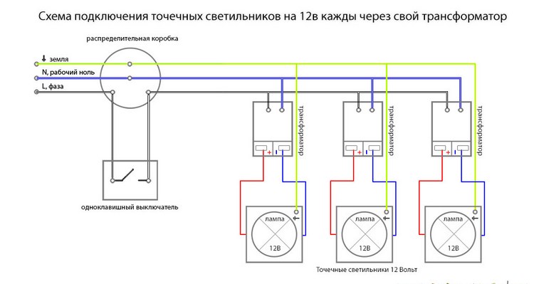
An example of a connection diagram of a step-down transformer 220 to 12 V:
To make it easier to wind coils (special equipment is used in factories for this), two wooden racks mounted on a board and a metal axis threaded between the holes in the racks can be used. At one end, a metal rod should be bent in the form of a handle.
 For simple tips on how to work, read the next review.
In 1891, Nikola Tesla developed a transformer (coil), with which he experimented with high-voltage electric discharges. How to make a Tesla transformer with your own hands, find out.
Useful and interesting information about connecting halogen lamps through a transformer.
Summary
- Transformer is called device with a core and two winding coils. At the input of the device, electricity is supplied, which decreases to the necessary indicators.
- The principle of operation of a step-down transformer is to create electromotive force that creates a magnetic field. The turns of one of the coils pass through this field, and the force of self-induction appears. The current changes, its magnitude and direction change. Energy is supplied by an alternating magnetic field.
- Such a device is needed for energy conversion, which prevents the combustion of electrical equipment and its failure.
- The assembly procedure for such a device is very simple. First you need to do some calculations and you can get to work. So that you can quickly and easily make coils, you need to make a simple device from the board, racks and handles.
In conclusion, we bring to your attention another way of assembling and connecting a step-down transformer from 220 to 12 Volts: