For the designed device to work properly, careful selection of passive components is required. It is necessary to consider in detail the characteristics of the passive element base of the future device and the preliminary layout of the cases on the board.
Often, developers do not attach much importance to the working frequency domain of passive components when selecting the element base for a future device. This leads to unpredictable results. I want to note that this applies not only to high-frequency analog devices, since high-frequency signals have a strong effect on passive low-frequency components by means of galvanic communication or emitting. For example, a simple active low-pass filter on an op-amp can work as an high-pass filter when a high frequency is applied to its input.
Noise management in automation systems is vital because it can be a serious problem even in the best tools and hardware for collecting and casting data. Fortunately, simple devices and methods, such as using proper grounding methods, shielding, stranded wires, medium signal methods, filters, and differential amplifiers, can control noise in most measurements.
Frequency converters contain switching circuits that can cause electromagnetic interference. Of course, there is a possibility that this switching noise may cause intermittency in equipment in its vicinity. While most manufacturers take due care with respect to designs in order to minimize this effect, complete immunity is not possible. Some layout, wiring, grounding, and shielding methods make a significant contribution to this minimization.
Resistors
A high-frequency resistor has its own inductance, capacitance, and resistance. See fig. 5.
Resistors can be divided into three main types: wire, carbon composite and film. The wire resistor in its structure is a coil of high-resistance metal, from which its own inductance appears. Film capacitors have a similar structure, so film capacitors also have inductance. Inductive properties of film resistors are manifested to a lesser extent than wire ones. Film resistors up to 2 kOhm can be safely used in RF circuits.
We will see inductive coupling in this article. Picture. The level of disturbance depends on changes in current and induction of mutual coupling. Figure 1 - Inductive coupling - Physical representation and equivalent circuit. Frequency: the inductance is directly proportional to the frequency — the distance between the alarm cables and the victim and the length of the parallel cables. - The height of the cables relative to the reference plane.
Measures to reduce the effect of inductive coupling between cables
The load resistance of a cable or a disturbing circuit. Figure 2 - Inductive coupling between conductors. Figure 3 - Inductive coupling between cable and field.
Measures to reduce the effect of inductive coupling between cable and field
Figure 4 - Inductive coupling between the ground cable and the loop.Since the findings of the resistors are parallel to each other, therefore, there is a significant capacitive coupling between them. The larger the resistor, the lower the inter-terminal capacitance.
Capacitors
The equivalent circuit of the capacitor in the high-frequency region is shown in Fig. 6.
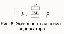
Figure 5 - Interference between cables: magnetic fields induce transient currents through inductive coupling between cables. Electromagnetic interference can be reduced. Figure 6 - Mutual inductance between two conductors. A twisted pair cable consists of pairs of wires. The wires of the pair are helically folded in order to reduce noise through the cancellation effect and maintain constant electrical properties of the medium along its entire length.
The number of braids in the threads can be varied to reduce the electrical connection. Due to its design, it provides capacitive coupling between the conductors of a pair. It has a more efficient behavior at low frequencies. When not shielded, it has a lack of noise in general mode.
Capacitors in circuitry are used as decoupling and filtering elements. To calculate the reactance of a capacitor, we turn to the following formula: 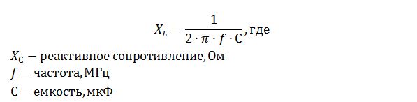
Based on the above formula, we calculate the reactance of a capacitor with a capacity of 10 μF at frequencies of 10 kHz and 100 MHz. The calculated values \u200b\u200bwere the following 1.6 Ohms at 10 kHz and 160 μOhms at 100 MHz. And now let's check it really.
Figure 7 - The effect of inductive coupling on parallel cables. Figure 8 - Minimizing the effect of inductive coupling on twisted cables. Figure 9 - An example of induction noise. Using twisted pair is very effective if the induction in each torsion region is approximately equal to the adjacent induction. Its use is effective in differential mode, balanced circuits and has low efficiency at low frequencies in unbalanced circuits. In high frequency circuits with grounded multipoint frequencies, the efficiency is high, since the reverse current tends to flow through an adjacent return.
All the resistances mentioned add up to create an equivalent series resistance (ESR). Based on the foregoing, we note that capacitors used in decoupling circuits must have a low ESR. This is because the series resistance limits the efficiency of suppressing ripple and interference. The increase in the operating temperature of the device also significantly affects the change in ESR, increases. Therefore, when using an aluminum electrolytic capacitor at elevated operating temperatures, it is necessary to use capacitors of the appropriate type.
Using the screen in inductive coupling
However, at high frequencies in normal mode, the cable is ineffective. Magnetic shielding can be applied to a noise source or signal circuit to minimize traction. Protective low-frequency magnetic fields are not as simple as shielding electric fields. The effectiveness of magnetic shielding depends on the type of material and its permeability, thickness and frequency.
Due to its high relative permeability, steel is more efficient than aluminum and copper at low frequencies. However, at higher frequencies, aluminum and copper can be used. Loss of absorption using copper and steel with two thicknesses is shown in the figure.
When using electrolytic capacitors, you should carefully position and connect the capacitor on the board. The positive lining should be connected to the plus, the lines connecting the capacitor should be as short as possible. If the capacitor is incorrectly connected, currents begin to flow through the electrolyte with an early failure of the capacitor itself.
Protection against the use of metal gutters
Figure 11 - Absorption loss using copper and steel. Magnetic shielding of these metals at low frequencies is very inefficient. Below we will see the use of metal channels in minimizing eddy currents. The distance between the channels facilitates the perturbation created by the magnetic field.
Ideal is that each segment with the maximum possible contact area should be attached, which will have greater protection against electromagnetic induction and even if there is a conductor between each segment on each side of the channel with the smallest possible length, to guarantee an alternative path to circuits, if there is an increase resistance at the joints between segments.
There are also devices in which the DC potential difference between two points can change its sign. In such cases, non-polar electrolytic capacitors are used.
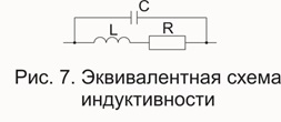
Inductance
An equivalent circuit of the inductance in the high-frequency region is shown in Fig. 7.
This reducing effect is lower at low frequencies. At higher frequencies, cancellation is more effective. This is the effect of plates and screens on the propagation of electromagnetic waves; they generate their own fields, which minimize or even negate the field through them, thereby functioning as true screens of electromagnetic waves. They function as a Faraday cage.
Protect the connection points from corrosion after assembly, for example with zinc or varnish. Although the cables are shielded, shielding from magnetic fields is not as effective as against electric fields. At low frequencies, twisted pairs absorb most of the electromagnetic interference. At high frequencies, these effects are absorbed by the cable screen. If possible, connect the cable trays to the potential equalization system.
Inductance reactance is described by the following formula:
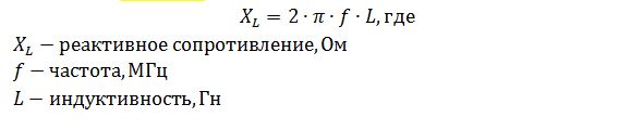
It can be seen from the formula that an inductance with a nominal value of 10 mH will have a reactance of 628 ohms at a frequency of 10 kHz, at a frequency of 100 MHz, the calculated value will be 6.28 MΩ.
Figure 12 - Transient protection using metal channels. Each automation design must consider standards to ensure an adequate signal level, as well as the security required by the application. Preventive maintenance is recommended annually by checking each connection to the grounding system, where the quality of each connection must be guaranteed in terms of reliability, reliability and low impedance.
Sensitivity analysis of electrical parameters of frequency-dependent transmission lines. In this work, a wide analysis of the sensitivity of the longitudinal and transverse electrical parameters of a three-phase transmission line as a function of frequency was performed. The actual 440 kV line was used as the basis for parameterization. In the sensitivity analysis, the following line characteristics were changed: the diameter of the lightning conductor cables, the phase diameters of the conductors, the height of the conductors, the horizontal distance between the phases and the geometry of the phase rays.
Printed circuit board
A printed circuit board also has all the described properties of passive components, but these properties are not so pronounced.
Printed conductors on a printed circuit board can be either sources of interference or receivers (antenna). Proper PCB tracing minimizes radiated and direct interference. Since any conductor on a printed circuit board can be considered as an antenna, we turn to the basics of the theory of antennas.
For each variation, we observed the behavior of parameters in terms of graphs of primitive matrices and in terms of modal components. As for modeling, the work will contribute to the development of new methodologies and simplified formulas for calculating the parameters used for the analysis of transient maneuvering processes.
Keywords: frequency dependence, mode domain, sensitivity analysis, transmission line, electromagnetic transients. In this work, a large analysis of the sensitivity of the longitudinal and transverse electrical parameters of a three-phase transmission line in the frequency domain was performed. The actual transmission line of 440 kV was used as a reference. In the sensitivity analysis, the following line characteristics were changed: the diameter of the ground wires, the diameter of the phase wires, the height of the conductors, the horizontal distance between the phases and the vertical distance in the external phase beam.
The basics of antenna theory
One of the main types of antennas is a “pin” or, in our case, a direct conductor. The full impedance of the direct conductor has resistive (active) and inductive (reactive) components:
![]()
For each line characteristic, the characteristics of electrical parameters in the frequency domain were observed in terms of primitive and modal matrices. Key words: frequency dependence, modal region, sensitivity analysis, transmission line, electromagnetic transient.
The study of the electrical parameters of power lines is of great importance for various areas of energy electrical systems, including the analysis of constant mode, as well as the phenomena of electromagnetic transients. One of the important aspects of linear modeling is related to the frequency dependence of the longitudinal parameters. Models with constant parameters are not suitable for simulating a linear response in a wide range of frequencies present during transients. In most cases, a model with constant parameters creates distortions that exaggerate the peak values \u200b\u200bof voltage and current.
At constant current and at low frequencies, the active component prevails. With increasing frequency, the reactive component is more significant.
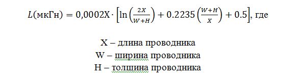
The formula for calculating the inductance of a PCB conductor is as follows:
It seems that not only the resistance varies with frequency, but also the inductance. This means that the frequency response of the line is different if the line is represented by a model with constant parameters or if the longitudinal parameters depend on the frequency. It can be argued that proper line modeling is essential for reproducing line behavior.
The longitudinal and transverse electrical parameters per unit length were calculated in the frequency domain for the real line considered in the base case. For this line, the parameter matrices were calculated in the domain of the phase region and mode. The calculation of the parameters was based on the theory of general knowledge, which will be briefly presented in the following articles.
On average, printed conductors on a board have an inductance of 6 ... 12 nH per centimeter of length. For example, a 10 cm long conductor has a resistance of 57 megohms and an inductance of 8 nH per centimeter. At a frequency of 10 kHz, the reactance becomes 50 MΩ, and at higher frequencies, the conductor must be considered as an inductance than a conductor with active resistance.
It was assumed that the transmission line was perfectly transposed, despite the inaccuracy of this hypothesis for high harmonics. Sensitivity analysis was done initially for the sections that make up the primitive line matrices and in the second stage for homopolar and non-homopolar modes.
The characteristics of the analyzed line were the linear geometry and the characteristic of phase conductors and lightning rods, namely: the height of the phase conductors, the height of the lightning rod cables, the horizontal distance between the phases, the geometry of the phase rays, the diameter of the lightning rods, the diameter and internal radius of the phase conductors.
The whip antenna begins to function when the ratio of the wavelength to the antenna length is 1/20. Therefore, a 10-centimeter conductor will serve as a good antenna at a frequency of over 150 MHz. Returning to printed circuit boards, I note that, for example, a clock generator may not have a frequency equal to 150 MHz, but higher harmonics from a clock generator can become a source of high frequencies.
The line has two lightning conductor wires at the top of the tower and 04 sub-conductors per phase. The longitudinal primitive matrix depends on the frequency and has its elements defined by the equation. Some simplifying hypotheses for modeling three-phase lines through primitive matrices were considered in: soil is flat near the line and is considered homogeneous with conductivity and a uniform dielectric constant; the final effects of the line are neglected in determining the electromagnetic field; the influence of structures is also neglected in the calculation of the electromagnetic field; ropes consisting of stranded and steel core threads are represented by a tubular conductor with a direct cross section in the form of a round crown, in which the current in the steel sheet is neglected.
Another one of the main types of antennas is a loop antenna. The inductance of the direct conductor increases significantly with bending. An increased value of the inductance of the conductor reduces the frequency at which the sensitivity of the "antenna" is maximum.
Experienced PCB developers who have an idea of \u200b\u200bthe loop antenna effect note that it is not possible to build the topology in such a way that a loop is formed for critical signals. Otherwise, loops are formed from the forward and reverse conductors. See fig. 8. The figure also reflects the effect of the slot antenna.
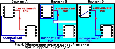
Take a closer look at the three options in Figure 8.
Option A: The most unsuccessful of those presented. It does not use land polygons, the loop circuit is formed by earth and signal conductors. It should be remembered that when the ratio of the wavelength to the conductor is 1/20, the loop antenna is quite effective.
Option B: Compared to Option A, this option is better. But here you can see the gap in the landfill. Forward and return current paths form a slot antenna.
Option B: This option is the best. The paths of the signal and reverse currents coincide, thereby the efficiency of the loop antenna is negligible. It is worth noting that in this embodiment, cutouts around the microcircuits are also present, but they are separated from the return current path.
The theory of reflections and matching of conductors is identical to that considered in the theory of antennas.
When the printed conductor is rotated through an angle of 90 °, signal reflection may occur. This is due to a change in the width of the conductor. In the corner of the conductor, the path width increases 1.414 times, which leads to a mismatch in the communication line, distributed capacitance and inductance of the path. Modern automatic design systems offer various types of smoothing angles, see fig. nine.
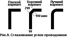
The best of the presented rotation options is the third option, since the width of its conductor is unchanged.
Introduction
Recently, the value of speaker cables, which no one had paid much attention to before, has begun to grow rapidly. If you used to think about cables last, now they have rightfully taken the place of full-fledged high-tech audio components, while cables are often covered with a completely unnecessary touch of mystery and mysticism.
Now on the market there is a wide selection of cables of various types corresponding to the most diverse needs. Unfortunately, consumers often come across a lot of confusing arguments and counterarguments that can turn any obvious merit of the cable into a monstrous flaw. This situation is exacerbated “thanks to” pseudo-scientific, and often simply mystical arguments used by the marketing departments of some companies.
This technical handbook summarizes in-depth research, including measurements and listening, conducted by QED, on the effects of speaker cables. Our goal was to develop a new line of high-quality cables, the design of which would be based on the results of these studies. The advent of the current line of speaker cables QED was a logical result of the research. We also received many lessons that influenced the design of our interconnect cables.
The listening was also very useful: QED engineers are well aware that the measurements themselves are only part of the picture. We would very much like to say that they provide all the necessary information, but this is not so. On the other hand, if the cable introduces errors and distortions that can be measured into the audio signal transmitted from the amplifier to the speakers, then obviously it cannot reliably play music.
QED believes that the cable should be as accurate, transparent and neutral as possible, and our cable design concept is based on the use of Genesis Report results as well as ongoing critical listening.
Cable value
At first glance, the speaker cable plays a very simple role, transmitting the signal from the amplifier to the speakers. But in practice, differences in sound quality when connected with different cables are clearly visible to most listeners, although some conservatives still believe that this can not be. Obviously, there are certain factors in cable design that affect sound quality.
Given that no component can improve the analog signal passing through it (or can only change or degrade it), the role of the speaker cable should be to transfer the audio signal between the amplifier and speakers without loss and nothing more.
Testing Basics
Since the speaker cable connects the components of the system, its assessment should not be carried out separately, but together with the amplifier and speakers. In fact, the speaker cable is a continuation of the amplifier circuit, it is equivalent to connecting additional components to its output, which have such electrical characteristics as: Resistance (R), Capacitance (C), Inductance (L) and Conductivity (G).
In most power amplifiers, their developers achieve reliable playback by comparing the output signal with the input signal. This design is called "negative feedback." Any error that appears at the output of a feedback amplifier is quickly corrected, because the amplifier automatically adds the same error, only with the return value to the input signal. Figure 1 shows that a negative feedback amplifier may try to correct errors that appeared before the feedback point. Errors at the input of speakers related to the influence of the cable are not corrected: the cable is outside the zone of influence of the feedback mechanism of the amplifier.
Some amplifiers take a feedback signal from the speaker switching terminals to take into account the influence of the cable, but such designs are extremely rare. One of the objective tests of the quality of an acoustic cable should include a comparison of the signal at the input (on the amplifier side) and at the output (on the speaker side). Any difference between them corresponds to a deterioration in the signal in the cable.
The real impact on the system
The terms that are used to subjectively describe the effect of the cable can be either positive, for example: “transparent”, “coherent”, “resilient”, “detailed”, “rhythmic”, or negative, for example: “grainy”, “screaming” , "Protruded", "nasal", "blurred." Our Genesis Report study showed that some of these characteristics can be predicted by analyzing the results of instrumental measurements. We tested many cable samples belonging to different price categories, using different technologies and marketing strategies for promotion, and took measurements for each cable, connecting it to a real load (speaker system)
 .The graphs presented in Fig. 2 and Fig. 3 show the amplitude-frequency characteristics. The upper graphs in the figures are plotted for the signal at the output of the amplifier, and the lower graphs after passing through the cable (at the input terminals of the speaker). The difference in signal quality between the two cables is obvious.
So, the bottom graph shown in Figure 2 is built for a flat cable with very low resistance (sample 10 in our test), and the bottom graph in Figure 3 illustrates the effect of a cable with double monolithic conductors (sample 7). The wave-like shape of the graph is associated with changes in the load impedance in the audio frequency range, which lead to the fact that the signal voltage "meets" with different values \u200b\u200bof the cable impedance at different frequencies.
The difference between the upper and lower curves in both graphs, in fact, characterizes the losses in the cables. Obviously, the losses are greater in the cable shown in Figure 3, using monolithic conductors, due to the higher DC resistance. I must say that in this case it is not just an academic question, since these losses will affect the resulting frequency response of the speaker system (in this case, the changes reach -0.8 dB at a frequency of 200 Hz, as shown in Fig. 3).
 The obtained frequency response, shown in both figures, are typical for phase-inverter acoustic systems when a uniform sinusoidal input signal is applied to them. Real signals are not sinusoidal, but include many frequencies at the same time, in addition, the load that the speakers represent is complex (complex load means that voltage and current are not necessarily in phase). Therefore, in the cable when playing music, there will be much greater losses in the amplitude of the dynamic signal than it might seem based on the analysis of these graphs constructed for a uniform signal.
Considering the absolute evidence that low resistance is necessary in order to get the most equal performance when working with real speakers, we are very surprised by the common trend, which is moving away from cables with low resistance and the spread of cables with monolithic conductors with higher resistance. Moreover, in the marketing materials of manufacturers, one can often find the statement that the use of monolithic conductors with a small cross-sectional area can reduce the effect of the skin effect.
Skin effect
 A skin effect is a phenomenon that is usually associated with high frequency transmission lines. When alternating current flows through the conductor, an electromotive force (EMF) is induced in it due to changes in the magnetic flux. This leads to the fact that the current density in the center of the conductor decreases compared with the regions located next to its surface. As a result, the region through which the current flows decreases, because the current is diverted from the central region of the conductor to the surface. The result of the skin effect is an increase in the cable impedance at very high frequencies, which is associated with a narrowing of the effective conductive cross-sectional area (surprisingly, but unlike inductance, the skin effect does not introduce phase deviations into the signal, but increases the signal power loss in the cable).
In systems operating at radio frequencies (much higher than the frequencies of the audio range), the skin effect is a serious problem that is struggled with by covering the conductors with silver to reduce the resistance on the surface through which most of the current flows at high frequencies. In audio cables, the assumption that the effect of the skin effect deserves attention leads to the appearance of cables whose core diameter is the same or less than twice the effective depth of signal penetration (the depth at which the current density decreases by 63% of its normal value) by high sound frequencies. The main idea in this case is that such a cable will operate in a mode of reduced current density at all frequencies. This allows you to make the symptoms of the skin effect not so noticeable (but not eliminate it), but at the same time, the cable impedance increases at all frequencies.
There is a lot of debate about whether the skin effect is felt on the sound, most engineers generally question its existence at sound frequencies. In order to objectively evaluate its value, we decided to conduct comparative measurements of the phase shift at high frequencies and chose four different cables. Two of them had a large diameter and a multicore structure, while the other two were of the “low skin effect” type and had a small cross-sectional area.
Initially, basic characteristics were measured, such as resistance, inductance, capacitance, and conductivity ( known as lumped parameters *) Then these values \u200b\u200bwere used to calculate the theoretical values \u200b\u200bof the phase shift during work with the load. It is important that these theoretical calculations do not take into account the skin effect and are based solely on lumped parameters. The result of these calculations is shown in Fig. 4.
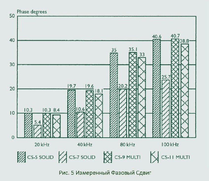
Then, the real values \u200b\u200bof the phase shift for each of the cables were measured at the same load. The results of these measurements are shown in Fig. 5. It can be seen that the theoretical and measured values \u200b\u200bare very close to each other, which is completely unexpected for those who consider the skin effect to be significant. Only at frequencies above 80 kHz can you notice a significant discrepancy between the theoretical and measured results for multicore cables (unless, of course, a value of 2% per 100 kHz can be considered significant).
This difference is due to two phenomena - the skin effect and, possibly, the proximity effect of neighboring conductors. The last of them consists in increasing the current density on the inner surfaces of parallel conductors and is more relevant for closely spaced tape conductors. Interestingly, the measured values \u200b\u200bof the phase shift turned out to be generally lower than the calculated theoretical values, since the skin effect, which is resistive in nature, increases the cable impedance during the passage of alternating current without introducing an additional phase shift. Surprisingly, the skin effect even reduces the phase shift, reducing the inductance of the cable. (For those who want to get a deeper understanding of this, we recommend that you turn to textbooks on the complex theory of alternating current).
Note that cable sample number 7 in Figs. 4 and 5 shows a smaller phase shift than the others, simply due to less inductance.
Inductive Effects
 The influence of inductive resistance on the phase shift of an alternating electric signal in a number of tested cables is shown in Figs. 6 and 7. The higher the inductance, the greater its influence on the magnitude of the phase shift. Familiarity with the geometry of each of the tested cables showed that most multicore cables have high inductance.
Cable inductance depends on the area of \u200b\u200bthe conductors, their relative location and the coefficient of permeability of the environment (materials with high permeability, such as iron or ferrite, for example, are used to increase the inductance in the inductor).
In cables, increasing the distance between the conductors leads to an increase in their inductance. Many multicore acoustic cables have conductors located far from each other (sometimes the distance between the conductors is 3 times their diameter), which leads to an increase in inductance.
By averaging the inductive effect for the studied cable samples, we obtained an effective phase shift of 0.42 degrees per meter. For a 10-meter length, the phase shift will be 4.2 degrees. In practice, the cable inductance is added to the output inductance of the amplifier (the output inductance is used to increase the stability of the amplifier at high frequencies), so that the resulting inductance of the amplifier is increased by the cable.
Auditory perception of a phase shift
Currently, the perception of a phase shift by ear is almost unexplored, although amplifiers with unimportant phase characteristics are often criticized for the “graininess” of the sound. Surprisingly, the phase shift of the amplifiers is not mentioned so often, although in a number of models on the market, one can encounter values \u200b\u200bof phase shifts exceeding 15 degrees at a frequency of 20 kHz.
Inductance and capacitance attenuation

Another effect associated with inductance is the weakening of the amplitude at high frequencies due to an increase in the impedance of the cable with frequency (inductive resistance increases with frequency). So, the higher the frequency, the weaker the signal arrives at the switching terminals of the speaker systems. Interestingly, cables with high inductance can also cause an increase in voltage at the speaker terminals due to the output signal of the amplifier. This is due to the complex relationships between inductive and capacitive resistances, as well as constant resistance, which can lead to the appearance of a weakened resonance. This can be a problem for electrostatic speakers, which represent a load with a higher capacity than conventional electrodynamic speakers.
An example of resonant attenuation of a signal is shown in Fig. 8 in comparison with a pure output signal of an amplifier. In this case, an increase in the cable impedance at high frequencies leads to noticeable signal level losses, adding to the own decline in the amplifier characteristics.
Dielectrics
 The conductors of the speaker cable are coated with insulation or dielectric to prevent short circuits. This inevitably leads to additional losses, since dielectrics absorb some of the energy. Losses in the dielectric are sometimes associated with the attenuation coefficient or the tangent of the loss angle in the dielectric (almost similar to the power factor) and they increase with frequency. In general, the higher the attenuation coefficient at a given frequency, the greater the power loss in the dielectric. A selection of absorption coefficient measurements in our cable samples is shown in Figure 9. It illustrates an unusually wide range of results.
All dielectrics also have a property called permittivity. The lowest permeability, not counting the vacuum, has air, which allows you to get the lowest loss among all known materials. The higher the permeability, the higher the loss and the higher the capacity. This is due to the fact that the dielectric constant determines how much the dielectric is permeable to an electric field, which basically determines the capacitance of a capacitor.
On the contrary, the lower the permeability (the closer to the vacuum) of the dielectric, the lower will be the loss and capacity. If we take a vacuum as a reference point with a dielectric constant equal to 1, then we can introduce a dielectric constant for any dielectric. For example, air will have a dielectric constant of 1.0006, which by and large is similar to vacuum for any practical application.
The dielectric constant (Er) and loss (Tan d) for several popular cable insulation materials are given below:
| Insulation material | Er | Approximate 10 kHz Tan d |
|---|---|---|
| Polyvinyl Chloride (PVC) | 4,0 - 8,0 | 0,01 - 0,05 |
| Polyethylene | 2,6 | 0,0002 |
|
Polypropylene |
2,25 | 0,0004 |
|
Polytetrafluoroethylene |
2,1 | 0,002 |
| Air (for comparison) | 1,0006 | Almost 0 |
| Vacuum (for comparison) | 1,0000 | 0 |
Capacitance is also determined by the diameter and gaps between the conductors. The larger the gap between the two conductors in a given dielectric, the smaller the capacitance (the opposite is true for inductance). Looking at the table above, it is easy to see that it is almost impossible to make a cable with low capacitance and inductance using a low-quality dielectric.
Most cheap cables, including many of the ones we tested, used PVC insulation, which increased their own capacitance and dielectric loss in the cable. No matter what you do with the diameter and the distance between the conductors, such cables will necessarily have problems associated with either high capacitance or high inductance, or both.
Cable conductivity
Another property of dielectrics, which affects the operation of the cable and is associated with dielectric loss, is conductivity (G). Conductivity determines how well the conductors are insulated from each other. The lower the conductivity (G), the higher the insulation resistance (Rp). Better dielectrics are better insulators, since they contain fewer "free" electrons that carry electric current through the dielectric material when an electrical signal is transmitted through the cable.
Effects related to capacity
 In theory, the cable capacity should not seriously affect the operation of the audio system, since the cable is connected to a source with a very low resistance (as a rule, Ohm fractions for most power amplifiers). Although the capacitance is a kind of low-pass filter when connecting a cable to a source with such a small impedance, its effect on the frequency response is usually negligible. More importantly, the excessively high capacity of the speaker cable may indicate poor dielectric quality and high dielectric loss.
Some esoteric cables use several independently insulated parallel cores forming two conductors. With a certain geometry and use of low-quality materials, such a design can lead to an increase in capacity to a very high level. One of these cables, found among our test samples, had a capacitance of about 1375 pF (for comparison, the average capacitance for other 10-meter samples was of the order of 500 Pf).
Another factor to consider is amplifier stability. In some cases, a small excess capacity at the output of the amplifier can cause it to oscillate, overheat, or even burn out. Also, the amplifier can begin to briefly oscillate at radio frequencies during operation, without showing any noticeable symptoms. Well-designed amplifiers usually have a significant margin of power and resistance to phase distortion, so that a small additional phase shift due to increased capacitance does not lead to such problems. Unfortunately, some commercially available amplifiers do not have the stability necessary for stable operation under abnormal conditions, and it is in them that there may be problems associated with the use of long cables with large capacitance. The irony of this situation is that the inductance, as a rule, remains low in cables with high capacitance, which leads to an even greater decrease in the stability margin of the amplifier. Even if the amplifier has not fully transitioned to unstable mode, the sound quality may suffer, the sound becomes coarse and bulging due to the amplifier working at the very threshold of transition to unstable mode. Figure 10 shows the instability caused by the use of a cable with high capacity, which manifests itself in the form of ringing when transmitting a high frequency square wave.
Capacitance and inductance
If we consider one pair of conductors in a specific dielectric, then reducing the distance between them, we will reduce the inductance and increase the capacitance, while increasing the distance between the conductors will lead to the opposite effect. Many believe that it is impossible to deal with this trend and that the cable inductance cannot be reduced without increasing capacity. In fact, this statement almost became a kind of folklore law in the audio industry. However, comparisons made for conductors with different geometries, even if they had the same effective cross-sectional area (and therefore the same DC resistance) and the same dielectric materials, showed that this is possible by simply changing the relative position and configuration of the conductors (see Table 1).
QED Profile8 Qudos (QED Original)
Here are the results of cable tests conducted during the work on the Genesis Report and illustrating the enormous influence of cable geometry. Resistance, inductance and capacitance were measured for standard cables of the Qudos and Profile 8 series. The standard Qudos cable consists of two bundles, each of which consists of 79 cores with a diameter of 0.2 mm and has a figure eight cross-section. Profile 8 consists of eight bundles, each of which consists of 19 cores 0.2 mm thick and has linear cross-sectional geometry. The effective cross-sectional area of \u200b\u200bthese cables, and therefore the DC resistance, are approximately the same. Both cables use low density polyethylene insulation. Therefore, any differences in inductance and capacitance are related to geometry.
Profile 8 cable can be connected in various ways. Table 1 shows the results when using four internal and four external conductors, as well as four left and four right conductors, as the direct and return wires of the cable. Compared to the standard Qudos cable, Profile 8, in the configuration of the four outer and four inner conductors, has a significantly lower inductance and slightly larger capacitance, which contradicts the “rule of thumb” that is often quoted. Conversely, in a configuration using right and left conductors, Profile 8 has the same inductance as Qudos, but the capacitance is almost halved. It is also of interest that geometry affects wave impedance, however, this interest is purely academic in nature.
Acoustic Channel Interpenetration
 One of the subjective effects that listeners often pay attention to is to expand the soundstage when using any particular cable. At first glance, explaining this phenomenon is quite difficult, given the high electrical isolation between the stereo channels. We thought that the explanation could be that the right and left channels are acoustically connected through the speakers themselves. Ideally, the left speaker should emit a sound wave only under the influence of the electrical signal of the left channel and vice versa.
Ideally, an electromagnetic damper with its own loudspeaker should be used in each amplifier channel, which prevents its diffusers from moving under the influence of sound waves from another loudspeaker. This damping should be achieved due to the very low output impedance of the amplifier, but in practice the resistance of the speaker cable interferes with the process, which increases the value of the impedance of the amplifier that the loudspeaker “sees” and accordingly reduces the damping. Thus, in the sound emitted by the diffusers of each speaker, there is a signal (with a certain delay), which was reproduced by another speaker, which leads to a narrowing of the sound stage. If this assumption is true, then cables with low resistance will allow you to build a wider sound stage.
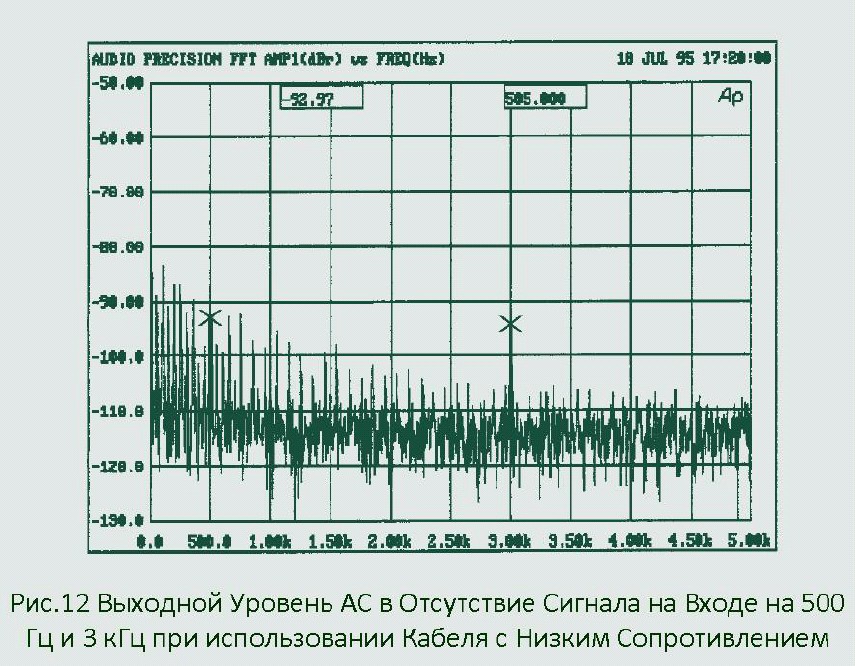
Despite the fact that these arguments seem too complicated, the voltage measurements at the speaker terminals shown in Figs. 11 and 12 illustrate just such an effect. The peak values \u200b\u200bmarked with crosses represent the amplitudes of the signals generated by the movements of the diffuser of the speaker system, which does not receive an electrical signal, which are caused by the fact that the speaker system of the other channel reproduces the test tone. The voltage at the speaker switching terminals, measured when another speaker played a test tone with a frequency of 500 Hz, decreased by about 10 dB due to the use of a cable with a lower resistance (Fig. 12).
Transient characteristics
 As mentioned earlier, acoustic systems in the general case are a very complex electrical load, which itself also generates voltage (both under the influence of sound waves penetrating from the outside and due to the energy remaining in the oscillatory system of the speaker itself), which returns back to the amplifier (This phenomenon is also known as reverse emf). This phenomenon can occur in the cases described in the previous section, as well as with rapid changes in the signal amplitude, leading to the appearance of after-sounds in the loudspeaker - i.e. the presence of sound in the absence of an input electrical signal from the amplifier. The amplitude of these after-sounds depends on the combined ability of the amplifier and cables to damp and control unwanted residual vibrations. Figure 13 shows the time dependences of the voltage at the output of the amplifier and at the input of the speaker systems. It is clearly seen that after 2.4 milliseconds, when the voltage at the output of the amplifier drops to zero, the voltage at the input of the acoustics goes into the negative region, then it starts to increase, goes over the zero mark, becomes positive and only then drops to zero. This voltage behavior at the speaker terminals is associated with unwanted movements of the diffuser. AC.
 Fig. 14 shows graphs for the same speaker, but connected with a cable with less resistance. The fact that the measurement results got better is completely obvious. Cable inductance also increases the overall impedance between the amplifier and speakers, and our measurements have shown that cable inductance has a negative effect on transient reproduction. A complex electromechanical loudspeaker system works best if it is well damped and connected with a cable with the lowest possible impedance in the entire frequency range, and not just at low frequencies, at which the movements of the diffuser are controlled by the value of the DC resistance.
Cable Distortion
 The speaker cable “distances” (in electrical terms) the loudspeaker from the amplifier for several reasons - due to electrical resistance to direct current, which spoils the frequency response, damping and separation, as we found. In addition to this, measurements showed that the amount of distortion at the input of the speaker is much larger (especially the second harmonic) than at the output of the amplifier.
 We found that the deterioration in the quality (and reliability of the transmission of the original signal) is highly dependent on the constant resistance of the cable, as well as the type of speaker systems. In Fig. 15 and 16 show the dependences of the amplitude of the second harmonic of the signal on frequency. The upper curve in each of the 2 graphs shows the distortion at the input of the speaker, and the lower one at the output of the amplifier. In Fig. 15 (a cable with a high resistance of the order of 0.065 Ohm / m), the distortion value is approximately 3 times greater than in Fig. 16 (cable with a low resistance of the order of 0, 004 Ohm / m).
 In Fig. 17 shows the relationships for different speakers connected by the same cable. Note that the cable itself cannot cause distortion (since its constant resistance is almost linear), rather, its presence in the system does not allow the amplifier feedback mechanism to accurately correct distortions that are generated due to various nonlinear phenomena inside the audio system.
Connecting the amplifier directly to the speakers allowed for very accurate distortion correction. Further studies are needed, but it is very likely that distortion at low frequencies is also partially affected by the resonant frequency of the speaker enclosure.
In addition, it must be said that the amount of distortion at medium and high frequencies increases significantly with increasing cable inductance, which increases the cable impedance and therefore reduces the damping effect of the amplifier and cable on the speaker system.
Distortion in multicore and single-core cables
 There is a point of view that in multicore cables, the so-called diode effect is observed, which appears due to the fact that the current “jumps” between the cores in the cable, and thus when electrons move from one end of the wire to the other, they also pass through many metal boundaries oxide-metal located between the conductors (sometimes this is also associated with the influence of the skin effect, which “squeezes” the electric current from the center of the conductor to the surface at high frequencies).
Making the assumption that the current really “jumps” between the conductors (for us it was completely unobvious, but as we discovered earlier, the skin effect does not significantly affect the audio signal in the acoustic cable), we applied a signal to the input of one conductor core and made measurements at the exit of another core. Even using all the resources of our Audio Precision AP1 measuring complex, we were not able to detect any increase in distortion compared to the result obtained using all the wires of the conductor (see Fig. 18). In both cases, the measurements showed such close results that they can easily be taken for two consecutive results of the same test. In this example, our assumptions were not confirmed. It seems that the diode junctions between the conductors either do not exist or are “short-circuited” by many good conductors, carefully pressed together along the entire length of the cable.
Wave impedance
This term is sometimes used in the context of audio cables, although it is primarily associated with transmission lines. Wave impedance is critical in determining the correct values \u200b\u200bof the load and source impedance in high frequency transmission lines to prevent unwanted reflections and standing waves. For correct operation, the transmission line must be equipped at both ends with a resistive load equivalent to the wave impedance.
Speaker cables are not transmission lines because their length is small in relation to the wavelength. In any case, speaker cables cannot be equipped with the same resistive load at both ends (the 8-ohm impedance at the amplifier output completely disrupts damping and leads to an increase in frequency response irregularities and an increase in distortion).
Directivity
Measurements designed to reveal the asymmetry of the tested samples, some of which were marked by the manufacturers as directional, did not confirm the existence of directivity of the speaker cables. Blind listening also showed that listeners were not able to distinguish the direction of the cables. On the other hand, it was found that the position of the cable affects both the measurement results and the listening results. This means that any measurements and any cable listening should be carried out with the same positioning of the cable under test.
Conclusion
Of course, there will always be people who are skeptical about the importance of speaker cables, but the results of our research have clearly shown that the quality of the system can improve or deteriorate depending on which cable is used in it. An analysis of the data showed how strongly the sound is associated with the measurement results.
Here are the generalized results of our research:
- Constant resistance.Low cable resistance is one of the priority values \u200b\u200bfor achieving high quality playback, but it should not be achieved due to other important parameters. High cable resistance leads to undesirable consequences, such as: unevenness of the frequency response, shortcomings in the transmission of transients, an increase in sound distortion, and a deterioration in channel separation.
All cables with high resistance had poor corresponding measurement results. Subjectively, their sound quality very much depended on the connected speakers. The protrusion of the middle frequencies, clearly visible by ear when connecting some cables, fully corresponded to the shape of their measured frequency response. High cable resistance also led to a noticeable smoothing of dynamic bursts during the transfer of large-scale musical compositions. - Inductance.Cable inductance is the primary cause of attenuation of high frequencies and the appearance of a phase shift. Inductance leads to an increase in impedance with frequency, and consequently, to a noticeable weakening of the high-frequency range of the signal at the input of the speaker system, and sometimes even to cutting off the peaks of the RF signal. In addition to this, the inductance increases the amount of distortion at the input of the speaker and worsens the overall transient characteristics of the speaker system. Thus, in order to obtain uniform frequency and phase characteristics, low distortion and a complete transmission of sound transitions by speaker systems, the inductance of the speaker cable should be low.
- Skin effect. Measurements showed that the skin effect has a minimal effect on cables with a relatively small cross-sectional area. At the same time, cables with thicker conductors are more susceptible to the effect of the skin effect, and also have a higher inductance, which leads to greater signal loss at high frequencies.
The effect of the skin effect becomes noticeable only at frequencies significantly exceeding the highest frequencies of the sound range. Despite the fact that the reactive impedance of a cable with conductors of a large cross section is higher than that of a cable with conductors of a small cross section, its effective resistance (the sum of reactive and constant resistances) will still be lower. The skin effect also has a somewhat unexpected side effect, which is to reduce the magnitude of the phase shift due to the inductance of the cable at high frequencies. - Insulation quality. The attenuation coefficient has been proven to be an eloquent indicator of sound quality. Most good-sounding cables use high-quality dielectric materials: PVC-insulated cables have shown the worst sound results. Cables with poor measured dielectric loss results were less capable of transmitting small parts and sound atmosphere, while cables with high-quality dielectrics reproduced them in full.
- Constancy of characteristics. Speaker cables interact with both the amplifier and speakers. In this regard, the measurement results obtained for some cables changed during the operation of cables in various systems. It turned out that the cables with the lowest resistance, inductance and capacitance possess the most stable characteristics. Despite the fact that the amplifier needs a certain inductance at the output to maintain stability, the use of the shortest speaker cables can improve the quality of reproduction. High cable inductance should also be avoided, as it can lead to unstable operation of the amplifier, ruin the sound quality and reduce the reliability margin of the amplifier.
- Directivity. Despite the growing love of manufacturers to indicate the direction of their cables, our measurements carried out under strictly controlled identical conditions did not reveal anything that could indicate that the speaker cables are directional. On the other hand, it was found that even a simple change in the position of the cable leads to a change in its inductance and capacitance.
- Monolithic and multicore cables. Recently, the popularity of single-core conductors has begun to grow. There is an opinion that a sufficiently thin monolithic conductor has approximately the same losses at both low and high frequencies, while for a thicker multicore conductor, their values \u200b\u200bdiffer significantly. Our studies have shown that this phenomenon is more likely due to the insulation and geometry of a number of cables with single-core conductors, which are the true reason for a higher quality of work compared to multi-core conductors. In any case, the parallel arrangement of the conductors, it does not matter, mono- or multicore, reduces the inductance, which has a much greater effect on the sound than the same skin effect.
The tested stranded cables had a higher inductance and greater leakage current than many of the stranded cables, which mainly used independently insulated conductors (which reduces the inductance) with higher quality dielectrics (which provides less leakage losses). We did not find any evidence of the popular theory that distortion occurs in multicore cables due to the diode effect between individual wires, so that it can be safely attributed to the category of false assumptions. - Metallurgy. Conductors made of copper with a high degree of purification (purity\u003e 99.99%) have slightly better electrical conductivity. A noticeable improvement in conductivity is observed in silver-plated copper conductors, as well as in silver conductors. In general, considering the entire group of cables we tested, we can say that geometry and dielectric materials have a much greater influence on the sound characteristics of a cable than the metal of which the conductors are made.
Genesis Report Results
The above generalizations (1, 2, 3, 4, and 5) showed that an speaker cable with the most accurate sound and stable characteristics should have a minimum constant resistance, inductance, and capacitance in combination with low dielectric losses. All the results of our research have confirmed this simple conclusion. Cables that use conductors with a small cross-sectional area in their design in order to get rid of the skin effect (which in any case does not present any problem at audio frequencies) have a higher constant resistance, leading to obvious negative consequences.
Thanks to the Genesis Report, QED engineers were able to refute the “rule” that established a direct relationship between inductance and cable capacitance. Capacitance and dielectric loss were reduced by choosing a suitable high-quality insulating material (low density polyethylene). In addition, by minimizing the thickness of the insulating sheath and special narrow joints between the conductors in the cable (providing greater mechanical stability), the ratio of air to continuous dielectric was improved, which further reduced capacitance and dielectric loss. By arranging several parallel stranded conductors in an optimal way, QED engineers were able to simultaneously reduce both the capacitance and inductance of the cable below the value calculated for a simple pair of conductors with the same constant resistance. The use of stranded conductors with a sufficiently high cross-sectional area allowed to maintain a low value of constant resistance. The result of research was the emergence of high-end speaker cables with low loss and transparent sound. The relationship between insulation quality and sound characteristics of the cable also influenced the design of QED interconnect cables, which use low-density polyethylene foam to increase the ratio of air to solid dielectric and get the best sound quality.

Scientific Approach to Cable Design
* system with lumped parameters
SYSTEM WITH FOCUSED PARAMETERS (discrete system) - a system, the movement of a swarm can be described as the movement of a finite number of point objects (strictly concentrated parameters) or extended objects with a rigidly fixed internal. structure (parameters reduced to concentrated). For example, a body suspended on a thread (pendulum), refers to S. s. n. if it can be considered point, and the thread is inextensible and weightless; hesitate. inductance circuit Lcapacities WITH and resistance Ris S. s. n., when the dimensions of all its elements are much less than the length of an e - magn waves and field structure in elements L, C and R can be idealized as rigidly fixed.
Description of S.'s movement with. The item is usually based on equations linking the generalized coordinates and generalized impulses (including fields, currents, voltages) of the objects included in it. The order of these urii is determined by the number of degrees of freedom of S. from with. n. So, the plane motion of a pendulum in the field of gravity or current changes in L, C, R-contour is described by differential. uriyami of the 2nd order and corresponds S. with. n. with one degree of freedom. Urniya of the movement of conservative (conserving energy) S. with. Items can be obtained from variats. principle (see Least action principle). In this case, three main type of equivalent descriptions of S.'s motion with. item: via Lagrange, the function containing generalized coordinates and velocities, through Hamilton, the function containing generalized momenta and coordinates, and q through the action (see Hamilton - Jacob and the equation)expressed through generalized coordinates and their derivatives. In the first two cases, ur derivatives include full time derivatives, in the latter case, partial derivatives.
Lit .:Andronov A.A., Vt t A.A., Xaikin S.E., Oscillation Theory, 3rd ed., M., 1981; Landau L.D., Lifshits E.M., Mechanics, 4th ed., M., 1988; Mandelstam L.I., Lectures on the theory of oscillations, M., 1972. M. A. Miller.