LED backlighting is increasingly being introduced into our lives. Moody bulbs fail and beauty immediately fades. And all because the LEDs can not work just from turning on the power supply. They must be connected through stabilizers (drivers). The latter prevents voltage drops, component failure, overheating, etc. This and how to assemble a simple circuit with your own hands will be discussed in the article.
Stabilizer selection
In the vehicle’s on-board network, the operating power supply is approximately 13 V, while most LEDs are suitable for 12 V. Therefore, a voltage stabilizer is usually installed, the output of which is 12 V. Thus, normal conditions for the operation of lighting equipment without emergency and premature failure are provided.
At this stage, amateurs are faced with the problem of choice: many designs have been published, but not all work well. You need to choose one that is worthy of your favorite vehicle and, in addition:
- will really work;
- will ensure the safety and security of lighting equipment.
The easiest do-it-yourself voltage regulator
If you don’t have a desire to buy a finished device, then you should learn how to make a simple stable yourself. It is difficult to make a pulse stabilizer in a car with your own hands. That is why it is worth taking a closer look at the selection of amateur circuits and designs of linear voltage stabilizers. The simplest and most common version of stability consists of a finished chip and a resistor (resistance).
Making the current stabilizer for LEDs with your own hands is the easiest thing on the chip. Parts are assembled (see the figure below) on a perforated panel or universal printed circuit board.
Scheme 5 ampere power supply with voltage regulator from 1.5 to 12 V.
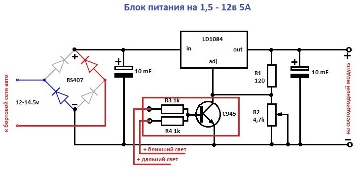
For self-assembly of such a device, you will need the details:
- plateau size 35 * 20 mm ;
- integrated circuit LD1084;
- rS407 diode bridge or any small diode for reverse current;
- power supply unit consisting of a transistor and two resistances. Designed to turn off the rings when turning on the main or dipped beam.
In this case, the LEDs (in the amount of 3 pcs.) Are connected in series with the current-limiting resistor, equalizing the current. Such a set, in turn, is connected in parallel with the next set of LEDs.
Stabilizer for LEDs on the L7812 chip in a car
The current stabilizer for LEDs can be assembled on the basis of a 3-pin DC voltage regulator (L7812 series). The mounted version is perfect for powering both LED strips and individual bulbs in a car.

Necessary components for assembling such a circuit:
- integrated circuit L7812;
- capacitor 330 uF 16 V;
- 100 uF capacitor 16 V;
- 1 amp rectifier diode (1N4001, for example, or a similar Schottky diode);
- wires
- heat shrink 3 mm.
There may actually be many options.
Connection diagram based on LM2940CT-12.0

The stabilizer body can be made from almost any material except wood. When using more than ten LEDs, it is recommended to attach an aluminum radiator to stability.
Maybe someone tried and says that you can easily do without unnecessary troubles by directly connecting the LEDs. But in this case, the latter will be in unfavorable conditions most of the time, therefore they will last a short time or even burn out. But tuning expensive cars translates into a rather large amount.
And about the circuits described, their main advantage is simplicity. For the manufacture does not require special skills. However, if the scheme is too complicated, then assembling it with your own hands becomes not rational.
Conclusion
The ideal option for connecting LEDs is through. The device balances the network fluctuations, with its use the inrush will not be terrible. In this case, the power requirements must be observed. This will allow you to adjust your stabilizer to the network.
The device should provide maximum reliability, stability and stability, preferably for many years. The cost of assembled devices depends on where all the necessary parts will be purchased.
In the video - for LEDs.
Motorists often wonder how to protect electrical consumers in a car that are powered by voltage. The failure of the 12-volt voltage regulator, which is installed in the generator, can damage an expensive car radio or tachometer, which is also powered by electric energy.
The situation described above was often found on classic domestic cars. In order to provide the electrical components of the car with high-quality voltage, which will not depend on the vagaries of the generator, it is better to use an autonomous automobile voltage regulator 12 volts. Even such popular tuning elements as LED strip, it is better to feed through this device.
To date, automotive models have been successfully used, whose design is based on chips of the KR142 series, which are designed to operate at a voltage of 12 V. They have the following markings: KR142EN12 and KR142EN18. The design of these microcircuits provides protection for the current that flows through them, as well as protection against overheating.
The numbers in the markings that appear after the letters ЕН indicate the rated voltage at which the microcircuit can work. In addition to the above, it is possible to use the KR142EN8V microcircuit in a car, but it will produce an operating current of 2.2 A, and it is greater than the first two options.
There are many options for connecting a 12 volt voltage regulator to the circuit in a car. The following figure shows the simplest example, which is quite acceptable for people who do not have much knowledge in electronics.

If during installation of the circuit the KR142EN18 chip is used, then the variable resistor R2 will need to be slightly adjusted so that the value of the output voltage is the correct value. Otherwise, the connection diagram is similar to that shown in the figure.
Resistors must be at least 0.05 W in power, since during operation it will depend on the difference between the input and output voltage values. The chip is installed on the radiator. The maximum current that can flow through the chip is 1.5 A. For the operation of the car radio, this current may not be enough, but other electrical devices of the machine can work fully. The described domestic microcircuits have an imported analogue - a microcircuit of the LM317T type.
You can connect it to an electric circuit using the same circuit. If there is a need to still connect a more powerful device and with a large consumption current that will be powered through a voltage regulator of 12 volts, then the problem can be solved by connecting several microcircuits in parallel. Thus, the current will be reduced.
The pulse device differs from those described above in its basic functions. It unstable current from an external source delivers short pulses to the inductor. Due to this, inductance stores energy, which passes into the load in the form of electrical energy, but has other voltage parameters.
Stabilization occurs due to the duration of pulses and pauses. Pulse devices have a high efficiency compared to linear ones. In other words, they can convert the input voltage according to predetermined parameters. You can adjust these parameters thanks to different options for drawing up an electrical circuit. The pulse converter may be step-up, step-down or invert.

The electrical network of the car is a very vulnerable part for all kinds of interference, surges or power surges. Interference can be created by the operation of the generator, unstable voltage, which depends on the state of the battery and engine speed. To protect the electrical network in cars use a pulse voltage regulator 12 volts.
Thanks to him, the unstable voltage at the input feeds the network with stable 12 volts and a current of about 0.3-0.4 amperes. The standard components of the machine, which are powered by electricity, are usually reliably protected during installation.
Power supply on the LM78H12K chip, 12 volts 5 amps
A powerful power source can be assembled on the basis of modern integrated circuits. Using the LM78H12K integrated circuit, a 12 V source with a maximum current of 5 A is obtained. The microcircuit has protection against short circuit and temperature rise and can withstand short-term currents of up to 7 A. This source can be used, for example, to power an ultrasonic scanner or other devices.
The source circuit is shown in Fig. 1.

The alternating voltage from the secondary winding of the transformer T1 is supplied to a powerful diode bridge VD1, designed for a rectified current of at least 5 A. After the diode bridge, the rectified voltage is supplied to capacitors C1 and C2, performing low-frequency and high-frequency voltage filtering, and then to the input of the stabilizer chip DA1.
The chip is made in a metal case TO-204 (TO-3) with two terminals (input and output). The case of the microcircuit serves as a control output and is connected to the circuit via screws and adapter pads on the printed circuit board. On this chip, you can assemble a linear voltage regulator operating in low dropout mode, with an output voltage of 2.3 V at a current of up to 5 A. From the output of the DA1 chip, the stabilized voltage is supplied to the capacitors C3, C4 and then to the output of the power source. The indicator on the HL1 LED performs service functions, i.e. shows the voltage input to the stabilizer circuit board.
The source circuit board (Fig. 2) is made of single-sided foil-coated fiberglass with a thickness of 1.5 ... 2 mm and a size of 60x60 mm.

The location of the radio components on the board is shown in Fig. 3.

After manufacturing the circuit board, current-carrying tracks, especially power ones, need to be well irradiated with solder. On the printed circuit board there is free space for installing a radiator when operating the microcircuit in extreme modes.

The types of parts used are shown in the table. The transformer for the source is selected in accordance with the current load and, it is recommended, with a secondary winding voltage of 17 ... 20 V. A fuse with a rated current of 0.5 ... 1 A must be installed in the primary winding of the transformer. The secondary winding of the transformer is connected to the printed circuit board thick stranded wire with good insulation, and as a network wire, a computer network cable with an euro plug is best suited.
At high loads, the diode matrix and the stabilizer chip are installed on radiators of appropriate sizes. For these purposes, the DA1 chip is specially located separately from the other radio components, this allows you to install a radiator with the required dispersion area. After mounting and testing the source, it is advisable to varnish the circuit board.
A selection of circuits of various power supplies for 12 volts for amateur radio designs and devices.
Mains voltage is supplied through the fuse to the primary winding of the power transformer. From its secondary winding, we remove the already reduced voltage by 20 volts at a current of up to 25A. If desired, this transformer can be made by yourself on the basis of a power transformer from an old tube TV.
From the secondary winding, a voltage of 20 volts goes to the rectifier bridge on the MV356 bridge assembly, because it is designed for a current of up to 35 Amps. Ripples are smoothed out with a capacity of 22,000 microfarads; you can use several capacitors connected in parallel, so that the total is at least 20,000 microfarads.

The constant voltage on the capacitance C1 in idle is about 26 volts. The stabilizer is built on an LM723 chip and an output regulator on VT1-VT5 bipolar transistors. Resistors R5-R8 are designed to balance the current potentials passing through transistors. The resistances included in the emitter circuits of the transistors are used to automatically set the base-emitter voltages under the action of the load current.
The output voltage is adjusted using the resistance R3, which together with the resistors R2 and R4 is an output voltage divider.
The internal comparator of the stabilizer chip works so that the voltage at terminal 10 is adjusted so that the voltage at its fourth terminal does not change.
To generate a maximum load current of 20A in the circuit, a current amplifier is required, on bipolar transistors VT1-VT5.
It is possible to adjust the maximum output current if one variable resistor with a nominal value of about 10-100 Ohms is connected in parallel with the low resistance R9-R12, and the control voltage is obtained from its slider and one of the two extreme terminals. Resistance will be a voltage divider on R9-R12. But in this case, the resistance R9-R12 must be calculated on the lower limit of the adjustment of the maximum load current. With the help of this resistance, you can still adjust the trip current of the protection.
The circuit provides a fairly good stability of a given output voltage.
VT2-VT5 transistors are required to be installed on volume radiators providing their excellent cooling. You can even use a radiator in combination with a fan.
In the first circuit, the voltage from the network goes to a step-down transformer through a 7A fuse-link FU1. Protective V1 should be at 240 volts. The transformer lowers the voltage on the secondary winding of at least 15 volts and with a load current of 5 amperes.

The reduced voltage from the secondary goes to the diode bridge, an electrolytic capacitor is installed at its output to smooth the ripple. VD5 and VD6 diodes are protective to prevent the discharge of capacitors C2 and C3 from a slight leakage current in the LM338 controller. C4 is needed to filter the RF component of the PSU. For normal operation of the circuit, the LM338 voltage stabilizer must be mounted on a radiator.
The second similar design of a powerful 12 volt and 5 ampere power supply is made on the stabilizer 7812. Since the permissible maximum load current of the microcircuit is only 1.5 amperes, a bypass external VT1 transistor is added to the design.

If the current in the load is below 0.6 Amperes, then it will go through the stabilizer 7812. If higher, then the resistance R1 will have a voltage above 0.6 volts, and the power transistor begins to pass an additional load current through itself. Resistance R2 limits excessive base current.
The power transistor must be placed on the radiator. Resistor R1 for a power of at least 7 watts. R2 is enough 0.5 watts.
Any computer power supply already has 12 volts, so it remains only to understand where they are. Black wires in the harness is a minus or a common wire. The yellow voltage is + 12V. So in order to get 12 volts we need to take only two wires from the power supply. It is worth considering that the 12-volt output channel is quite powerful and can "give" 8-10 amperes to a load (with PSU power up to 300 W.), in principle, in most cases it is enough.